Solving pavement failure from the ground down
Rutting and depressions in asphalt pavements occur when the underlying layers—base, sub-base, or subgrade—lose stiffness or compress under traffic loading. Causes include poor compaction, moisture ingress, fines migration, and settlement of variable fill or structure backfills.
Conventional rehabilitation methods such as milling and re-asphalting only reset the surface and fail to treat the ground beneath, leading to rapid recurrence.
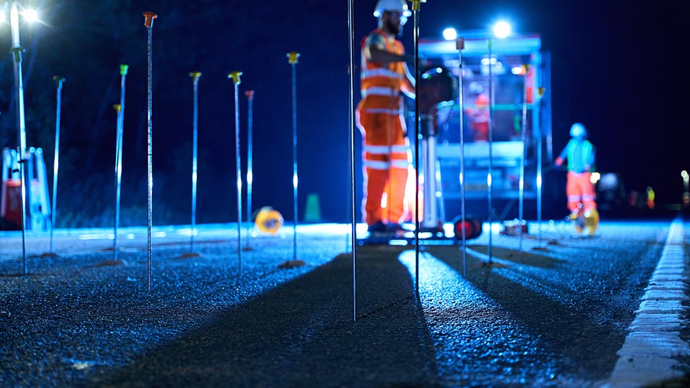
Geobear solutions address the root cause by delivering targeted treatments that densify and reinforce the soil or granular base. The process compacts the material matrix, fills voids, and increases bearing capacity. When needed, the pavement can be precisely lifted back to design grade—removing dips, bumps, or deformations—all with traffic still on diversion, not full closure.
Typical applications include highway wheelpaths, bridge approaches, intersections, heavy truck yards, airport pavements, and port access roads.
Why pavements fail in the UAE
In the UAE, pavement distress is rarely just a "surface issue." Whether it is flexible (asphalt) or rigid (concrete), the failure usually starts below ground.
Weak subgrade: Loose desert sands compact unevenly under heavy truck loads, causing wheel-path rutting and depressions.
Thermal expansion: Extreme heat cycles cause rigid slabs to expand and curl. If the subgrade support is weak, the slab corners snap (corner breaks).
Washout: Burst irrigation pipes or flash floods scour away the fines beneath the road, leaving the pavement bridging a void until it cracks or collapses into a pothole.
Reflection cracking: Movement in the base layers transmits stress upward, cracking the asphalt surface.
Technical mechanism
Ground strengthening
The expanding geopolymer applies localised compaction pressure (typically 50–300 kPa), improving inter-particle friction and density.
Void elimination
Injection fills microvoids and seals preferential drainage paths that promote fines pumping.
Composite reinforcement
The resulting soil–polymer composite has significantly higher stiffness and resistance to deformation.
Profile correction
Controlled injection pressure and real-time laser monitoring enable accurate lifting of the pavement surface (typically up to 30 mm).
Immediate load recovery
Treated zones regain full bearing capacity within minutes, allowing the road to reopen the same day.
Design and verification
All designs follow Eurocode 7 (EN 1997-1), international highway codes and best-practice geotechnical engineering methods. Finite-element (FEM) analysis and field calibration define treatment depth, spacing, and performance targets.
Design and verification
All designs follow Eurocode 7 (EN 1997-1), international highway codes and best-practice geotechnical engineering methods. Finite-element (FEM) analysis and field calibration define treatment depth, spacing, and performance targets.
Typical inputs
- Pavement cores and layer structure.
- FWD, DCP, or PLT data for pre-treatment stiffness.
- Groundwater and drainage review.
- Rut-depth and smoothness survey (flatness/IRI).
|
Parameter |
Typical improvement |
Verification method |
|---|---|---|
|
Subgrade stiffness (E) |
2–3× increase (e.g., 40 → 120 MPa) |
DCP / PLT testing |
|
Deflection reduction |
30–60 % decrease |
FWD or profilometer |
|
Rut depth correction |
≤ 2 mm tolerance after re-levelling |
Level survey / total station |
|
Settlement reduction |
> 60 % |
FEM validation |
Execution workflow
- Multi-level injection grid (0.8–1.5 m spacing).
- Injection depths typically 0.2–2 m below surface.
- Continuous lift monitoring via laser system (±0.5 mm).
- Verification by total-station resurvey after each injection pass
Monitoring and auality assurance
Trial area
A small pilot zone (2 × 2 m) is treated first to confirm response and material dosage.
Live laser monitoring
Each injection monitored by a laser target controlling adjacent reference points.
Incremental lift
Each lift pass limited to ≤ 4 mm to maintain surface integrity.
Post-survey
All control points re-checked after each stage to ensure uniformity.
Hole reinstatement
Drilling points sealed using epoxy mixed with asphalt dust for seamless finish.
Engineering Performance
Validated field projects show the following outcomes:
Stiffness (E-modulus)
2–3× improvement in treated zones.
Deflection (FWD)
30–60 % reduction after treatment.
Rutting / depression
Reduced to within design tolerance (≤ 2 mm).
Immediate reopening
Roads reopened to traffic within hours of completion.
Durability
No secondary rutting observed after multiple load cycles under heavy traffic.
Advantages over conventional repair
Treats the cause
Not the symptom: Strengthens the ground, not just replaces asphalt.
Non-disruptive
Up to 70 % faster and significantly cheaper than reconstruction.
Environmentally responsible
Up to 75 % lower CO₂ impact; minimal waste.
Fast and cost-efficient
Up to 70 % faster and significantly cheaper than reconstruction.
Durable and long-lasting
Water-resistant, chemically inert material with ≥120-year design life.
High precision
Laser-guided control ensures consistent results and prevents over-lift.
Applications
Highways and expressways
Correct wheelpath ruts and subsidence without closure.
Bridge approaches and transitions
Eliminate long-term settlement at abutments.
Industrial and port pavements
Increase bearing capacity for heavy vehicles.
Airport taxiways and aprons
Reinforce ground under repetitive high wheel loads.
Urban roads and bus corridors
Remove depressions at crossings, stops, and intersections.
Seeing cracks or dips in your road network?
Fix the root cause, not just the surface. Contact our engineers for a subgrade stability assessment.

