Two pre-treatment dynamic cone penetration testing (DCPT) profiles showed that ground resistance varied with depth and between the test locations. The lowest-resistance interval identified in the assessment was approximately 3.0 to 4.5 m below ground level. The combined mean N60, the processed indicator used to compare penetration resistance, was 6.28 in this interval before treatment.
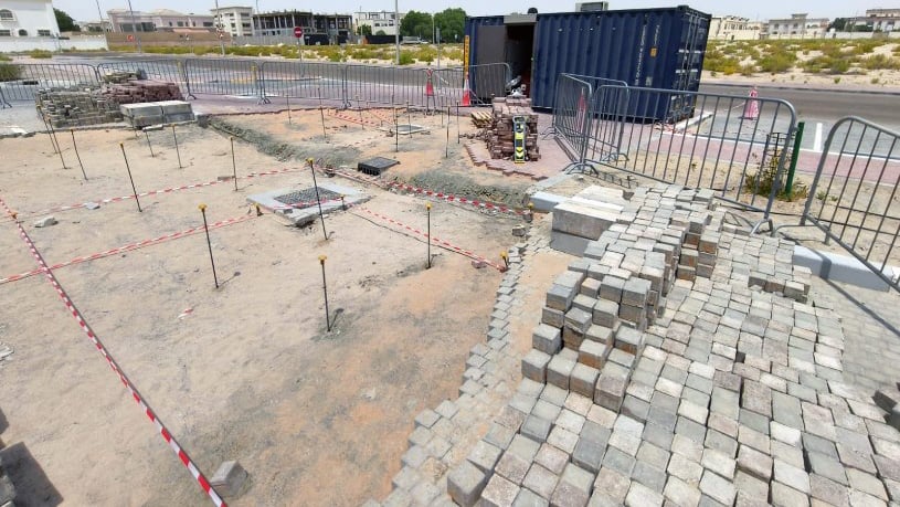
Electrical, drainage, plumbing and mechanical services ran beneath the paving. Manholes and drainage grates also constrained where the team could drill. Geobear had to place drilling points around those features, control access to the working areas and monitor the pavement for movement.
Interpreted ground model
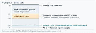
Figure 1. Interpreted ground model based on DCPT and independent surface-wave surveys.
The model shows the weak interval identified in the paired tests and the depths covered by the verification evidence. The ground may vary between test locations. Soil types and layer boundaries remain undetermined.
Geobear designed a solution to improve ground support beneath the existing pavement while keeping the facility operational. The team used staged injection through local drilling points in three pavement areas. The completion record lists 61 injection locations. During treatment, the team observed ground behaviour and monitored the pavement for surface lift.
Before drilling, Geobear used ground-penetrating radar (GPR) and a cable avoidance tool (CAT) to locate buried services. The team adjusted the drilling positions around the detected services, manholes and drainage features. Site controls included marked work areas, controlled access, equipment checks and service-location checks.
An excavation-and-replacement approach would have required opening the paving, working around buried services and reinstating the affected surface. Staged injection let Geobear reach the weak ground through local drilling points. This limited the working footprint at a facility that needed to remain in use and had limited space around its services.
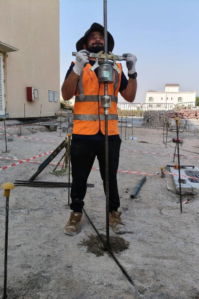
Installing an injection tube at a treatment point.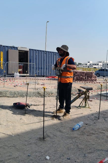
Injection works within a marked work area.
Geobear compared paired DCPT profiles at two locations. The processed dataset reports N60 at 0.1 m depth intervals. Combined mean N60 rose from 11.44 to 16.32 across the assessed depths, an increase of 42.7%. Both test locations recorded higher mean N60 values after treatment.
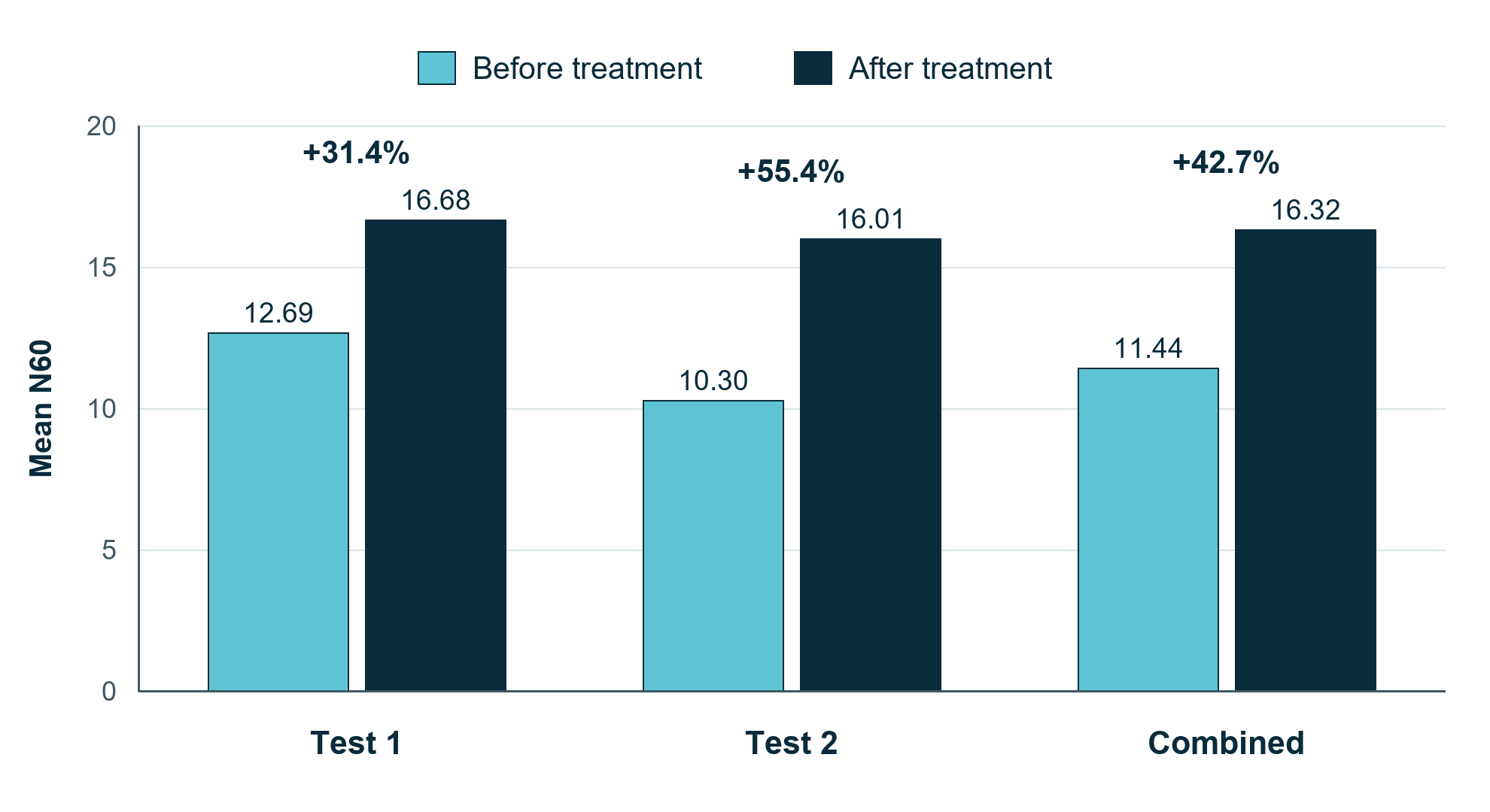
Figure 2. Mean N60 before and after treatment across the assessed depth intervals.
|
DCPT assessment |
Mean N60 before | Mean N60 after | Increase |
|---|---|---|---|
| Combined assessed depths | 11.44 | 16.32 | +42.7% |
| Initially weak interval (3.0–4.5 m) | 6.28 | 15.69 | +149.8% |
| Test 1 (1.6–7.5 m) | 12.69 | 16.68 | +31.4% |
| Test 2 (1.0–7.5 m) | 10.30 | 16.01 | +55.4% |
The strongest response was in the initially weak 3.0 to 4.5 m interval, where combined mean N60 increased from 6.28 to 15.69. Across both profiles, N60 improved at 88.9% of the assessed depth points. The paired tests show how penetration resistance changed at those locations.
An independent geophysical survey compared multichannel analysis of surface waves (MASW) sections before and after treatment along three lines. MASW estimates shear-wave velocity, which helps interpret variations in ground stiffness along a survey line. Each pair uses a common velocity scale for comparison.
The independent assessment confirmed improvement to approximately 7.0 m below ground level. The MASW sections show conditions along the survey lines and complement the penetration-resistance measurements at the two DCPT locations.
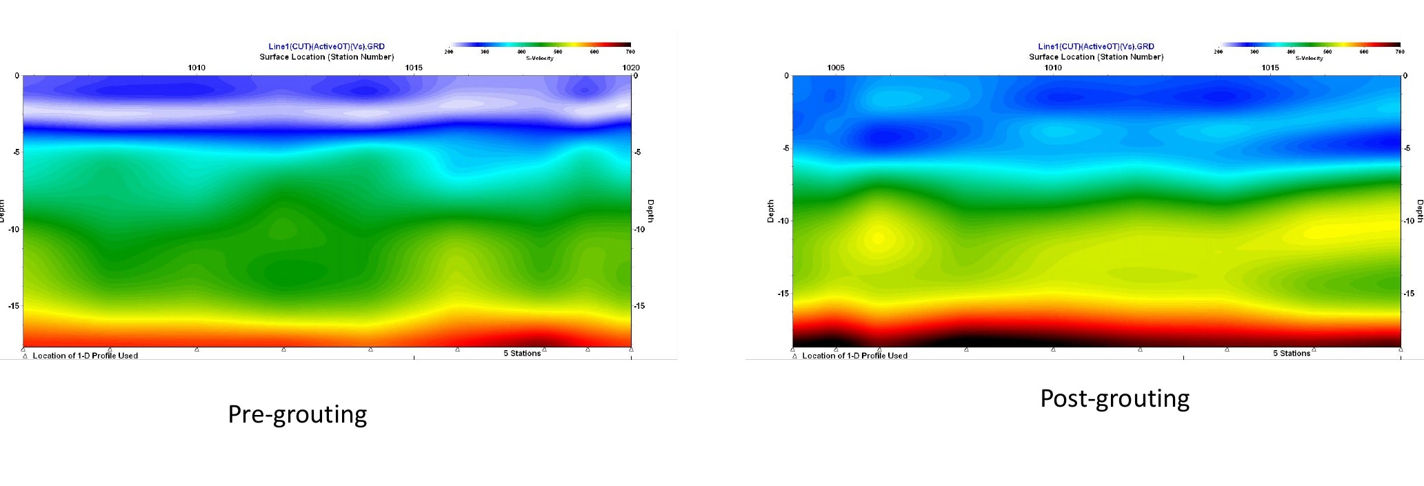
Figure 3. MASW survey line 1 before and after treatment.
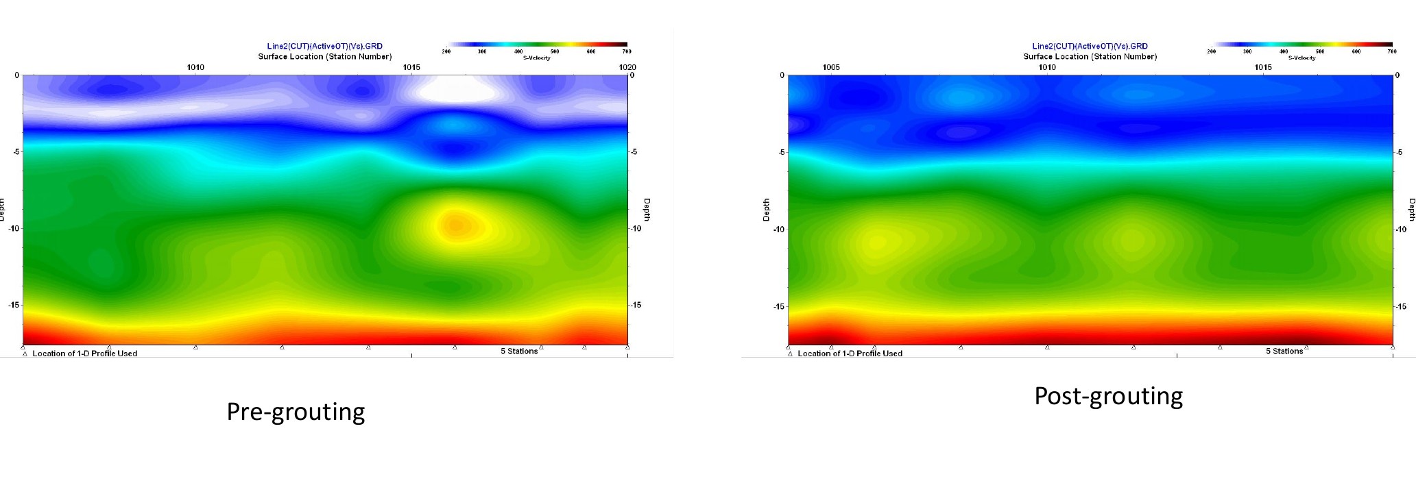
Figure 4. MASW survey line 2 before and after treatment.
Figure 5. MASW survey line 3 before and after treatment.
Don't let unstable ground put your business at risk. Our commercial team can provide a clear assessment and a fast, effective solution tailored to your operational needs.